
The modern manufacturing era features a relentless drive toward miniaturization. Across industries such as medical, electronics, automotive, and telecommunications, the demand for micro plastic components with impeccable precision is growing rapidly. Special consideration has to be given to all parts, but optical components even more so. This information is supplied by Brett Saddoris, Technical Marketing Manager of Accumold, based in Ankeny, IA, USA and edited by Andy Pye.
Achieving tight tolerances in micro moulding is a complex process that requires careful attention to every stage of production, from design through to assembly. Tolerances, measured in microns, are crucial and rely on expertise in several key areas: design, material selection, the moulding process itself, toolmaking, validation and metrology, and automated assembly.
Design phase
Micro moulding demands a unique approach to design, as the limitations and capabilities of the process must be considered from the outset. Traditional design principles cannot always be applied, with specific adjustments needed to avoid compromising on precision. For example, plastic materials shrink as they cool, and this shrinkage can vary, based on the polymer type and part geometry. In micro moulding, even a minute variation in shrinkage can lead to significant deviations in tolerance. Therefore, accurate modelling and compensation for shrinkage are critical.
Maintaining consistent wall thickness is essential for achieving dimensional stability. Variations in wall thickness can cause non-uniform cooling, leading to inconsistent shrinkage and resulting in tolerance issues. Micro-moulded parts often include features such as micro-channels or fine ribs. Even tight radii must be crafted with care to ensure that the mould can replicate these features without introducing dimensional inaccuracies. Draft angles, used to facilitate part ejection from the mould, must be carefully calculated to avoid warpage, while avoiding complex undercuts can help reduce the likelihood of tolerance issues during moulding.
Suitable materials
The material chosen plays a pivotal role in ensuring that the final part meets the desired tolerances. Different polymers exhibit varying degrees of shrinkage, flow characteristics, and mechanical properties, all of which impact the ability to achieve precision. High-performance thermoplastics like PEEK and liquid crystal polymers (LCP) are often preferred for their superior dimensional stability.
In micro moulding, the plastic must flow into very small, often complex mould cavities. Materials with high flowability are essential to ensure that every detail of the mould cavity is filled, preventing defects such as short shots or incomplete features. Additives like glass or carbon fibres, incorporated to enhance material strength or thermal properties, can also affect flow and shrinkage behaviour.
Processing
The moulding process itself presents its own set of challenges in maintaining tight tolerances. Achieving the necessary precision in micro moulding requires specialized machinery capable of controlling parameters such as injection speed, pressure, and temperature with extreme accuracy. Small deviations in these parameters can result in significant changes in part dimensions. For instance, if injection speed is too high or too low, it can affect how the material fills the mould, potentially leading to defects that affect tolerance. Similarly, maintaining consistent temperatures throughout the process is critical to avoid issues such as warping, shrinkage, or other dimensional inaccuracies.
Optimizing cycle time is also important: while shorter cycle times are often pursued for efficiency, in micro moulding, cooling time is particularly important to ensure that the part cools evenly and maintains its shape. Too short a cycle time can lead to parts being ejected from the mould before they have fully cooled, resulting in warping or dimensional inaccuracies.
Work smarter and win more with powerful software to manage regulatory, supply chain and sustainability challenges, learn more about ULTRUS here!
Tooling
Tooling is the foundation of micro moulding, and achieving micron-level tolerances requires a high level of expertise. The mould itself must be manufactured to extremely tight tolerances because even the smallest deviation can result in an out-of-spec part. Micro moulds often have intricate features, and maintaining consistency across all cavities within a multi-cavity mould is crucial for uniform part production. High-precision machining techniques such as electrical discharge machining (EDM) and CNC milling are used to create the intricate details required for micro moulds. Cooling channels within the mould must also be carefully designed to ensure even temperature distribution, as uneven cooling can lead to shrinkage issues that impact tolerances.
Validation and assembly
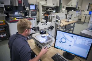
Once parts are produced, validation and metrology play a crucial role in ensuring that they meet the required specifications. Advanced metrology techniques are needed to accurately measure micro-moulded components, given their small size and intricate features. Traditional measurement tools are often insufficient for this task. Coordinate measuring machines (CMMs) and optical inspection systems are commonly used to verify the dimensions of micro parts with high precision. Micro computed tomography (Micro-CT) is another tool that allows for both external and internal features to be measured without damaging the part, which is especially useful for components with complex geometries.
Automated assembly processes equipped with vision-guided robots or alignment tools are desirable to ensure that these delicate parts are handled with the required precision. Human error in assembly can introduce variability that affects tolerances.
Optical components – special considerations
Augmented reality (AR) is rapidly advancing across industries, from consumer electronics and entertainment to healthcare and industrial sectors. Central to the functionality of AR devices are the optical components, which must provide clear, undistorted images and seamless digital overlays onto real-world environments. Given the short optical paths in AR systems, even the slightest deviation in the position or shape of these components can lead to significant image distortions or misalignment.
Head-up displays (HUDs) are used in automotive and aviation to project important information onto the windshield, such as speed and navigation data. Micro-moulded lenses and light guides ensure the projected image is clear and properly aligned with the user’s line of sight.
AR smart glasses are designed to overlay digital content onto the wearer’s real-world view. These devices require optical components that are not only highly precise but also compact and lightweight.
AR systems are used to overlay imaging data onto a patient during surgery or diagnosis, helping medical professionals to visualize internal structures in real time. Self-evidently, the optics used in these systems must be extremely precise.
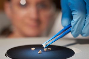
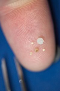
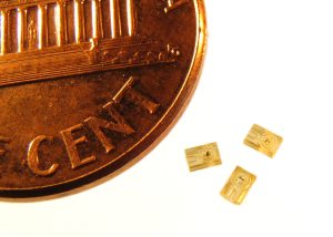
Micro moulding is emerging as a key technology in meeting these demands. The process enables extremely small components to be produced, ranging from 20mm to 1mm in size.
Custom moulding machines for micro-optics
Standard injection moulding machines are generally not able to produce micro-optic components Custom moulding machines are equipped with advanced features that allow for the precise replication of small optical elements with micron-level accuracy.
For example, refractive micro lens arrays used in AR applications often measure less than 100mm, Similarly, DOEs, which are crucial for controlling light in AR devices, have surface features measured in nanometres.
We help companies mitigate risk and earn trust among stakeholders to whom companies demonstrate health and sustainability in their product lines, facilities and supply chains, learn more about Sustainability and Environment services here!
Specific challenges for optical parts
While micro moulding offers many advantages in the production of AR optics, there are also challenges that must be addressed. Tooling must be designed with extreme precision to produce the complex geometries and surface features required for micro-optic components. Creating high-precision moulds is critical in ensuring that the final parts meet the necessary optical standards.
Materials selection is another challenge, as the polymers used for AR optics must offer both optical clarity and durability. In addition, they must be capable of maintaining their properties over time, even when exposed to environmental factors such as UV light and humidity. Micro moulding allows the use of advanced optical materials, including polymers that are specifically formulated for optical applications.
In addition, the assembly of AR devices that incorporate micro-optic components is often complex, as these parts are extremely small and delicate. To mitigate this challenge, micro moulders use automated assembly techniques that reduce the risk of contamination and ensure precise alignment of the components. Over-moulding, a technique in which multiple functions are integrated into a single moulded part, may also be used to simplify assembly and reduce the need for additional post-production steps.
Micro additive manufacturing (Micro AM)
Accumold has embraced the emerging micro additive manufacturing (micro AM). This technology complements traditional micro moulding by enabling complex geometries that are difficult or impossible to achieve with conventional methods. Furthermore, micro AM can be used to create direct rapid soft tooling (DRST), which significantly reduces lead times and costs for prototype and small-volume production runs with certain thermoplastics.
Further Information
Accumold www.accu-mold.com
The views, opinions and technical analyses presented here are those of the author or advertiser, and are not necessarily those of ULProspector.com or UL Solutions. The appearance of this content in the UL Prospector Knowledge Center does not constitute an endorsement by UL Solutions or its affiliates.
All content is subject to copyright and may not be reproduced without prior authorization from UL Solutions or the content author.
The content has been made available for informational and educational purposes only. While the editors of this site may verify the accuracy of its content from time to time, we assume no responsibility for errors made by the author, editorial staff or any other contributor.
UL Solutions does not make any representations or warranties with respect to the accuracy, applicability, fitness or completeness of the content. UL Solutions does not warrant the performance, effectiveness or applicability of sites listed or linked to in any content.